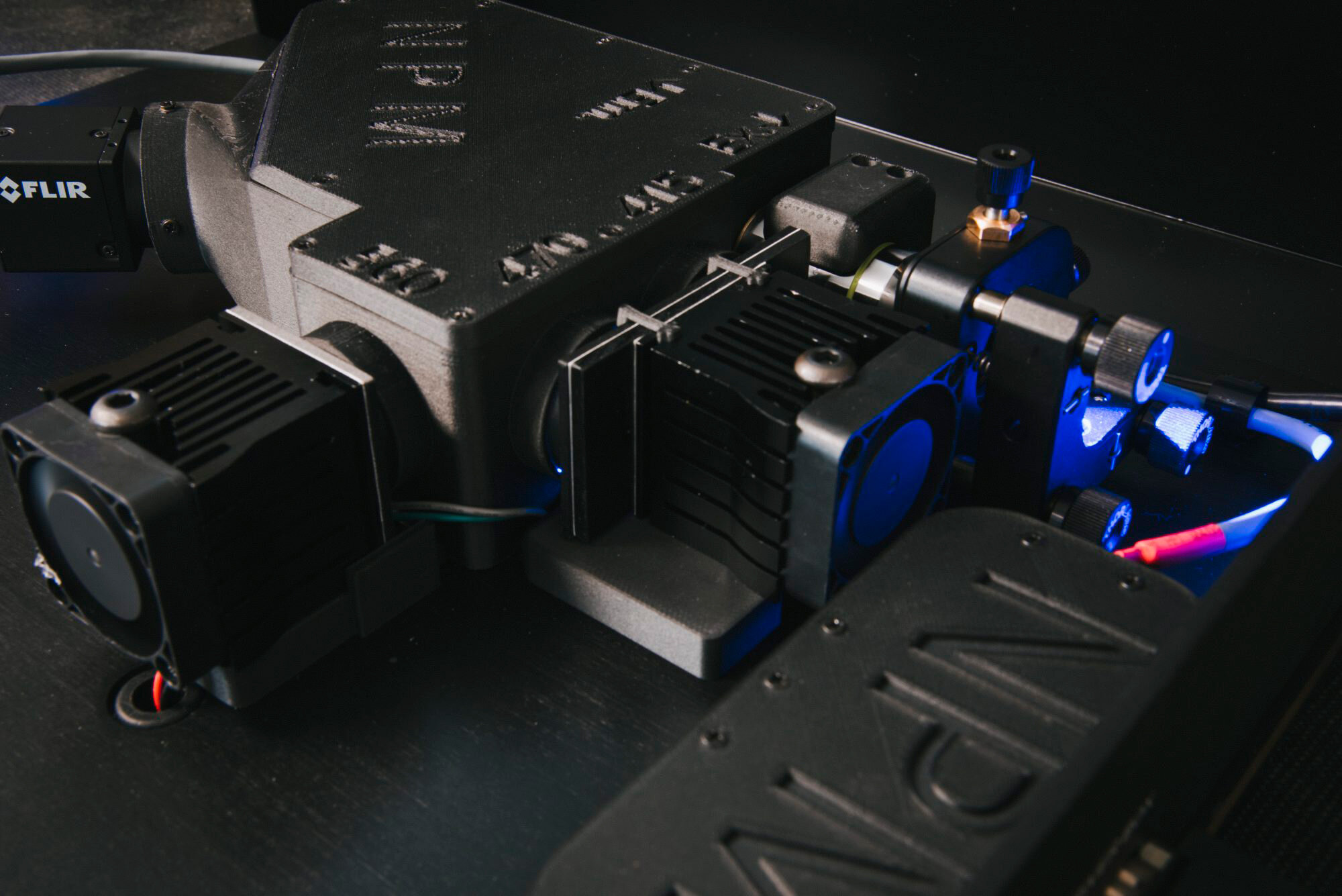
Evaluating Raw Fiber Photometry Data
One of the most common questions we get is: are these data that I’m collecting any good? Am I recording a decent signal, or is this noise that I can’t yet recognize in real time?
Here, we’ve laid out some important considerations to give you a jump-start on the road to learning how to identify good photometry data in real time. If you are brand new to fiber photometry, we recommend checking out our resources to get familiar with the basic concept behind the method.
Getting Connected and Checking for Signal
When you first connect your animal to your fiber photometry system, you’ll want to check to see if you have any fluorescent signal. To check for signal, you should configure your LED sequence to include the appropriate wavelengths for your sensors, then start the workflow and open the visualizer node. You will see a live depiction of your fluorescent trace. The x-axis of the plot represents time, and the y-axis represents the relative fluorescence of your indicator. Remember that this raw signal trace is a representation of the bulk fluorescence captured by the camera. The measurement of this signal is based upon the mean pixel value of each ROI recorded by the camera, or “F.” These are arbitrary units and will vary between subjects and recording sessions. Therefore, conclusions about the absolute strength of your indicator’s fluorescence cannot be drawn based solely on the numerical value reached on the y-axis of this live graph. To make accurate comparisons between recording sessions, experimental conditions, or other variables in your fiber photometry experiment, you’ll need to perform some post-hoc analysis.
However, it is possible to make some assessment of the quality of your signal during the recording. For example, if you are recording from a mouse in an open field, you may be able to see signal changes that correlate with events such as rearing or reactions to external stimuli. You may also be able to evaluate the kinetic features of your trace in relation to the known kinetics of your indicator. As a general rule, the kinetics of the these bulk signals cannot exceed the kinetics of the indicator; if you’re recording with GCaMP6s, for example, and see a peak with a rise time of 50ms, this peak exceeds the kinetics of GCaMP6s and is likely an artifact rather than true signal. Paying close attention to kinetics and correlations with the behavioral environment can impart some confidence that your signal is “real” and not merely the result of confounding variables, such as motion artifacts.
Recognizing Motion Artifacts
Signals may fluctuate as a result of activity-independent variables, like motion. Fortunately, there are some controls in place to identify motion artifacts, including the isosbestic signal. At the isosbestic point of GCaMP, fluorescent emission should be the same whether GCaMP is bound to calcium or not. Thus, any fluctuations in signal can be ascribed to motion or other non-calcium related events.
When recording in multiple channels, motion artifacts often appear in live traces as simultaneous deflections across all channels. This parallel motion is the result of both calcium-dependent and calcium-independent signal fluctuating in sync with each other, which suggests that the signal is not activity-dependent.
If you suspect that you are recording some motion artifacts, there are a few variables to check. The most common cause of motion artifacts is not a result of the brain moving relative to the implant, but rather the patch cord bending. Smooth out any sharp angles or kinks in the patch cord, and let it drape or hang in a way that bends as little as possible. Use the extra slack in the patch cord to absorb any twists that have occurred above the animal, and thoroughly untwist patch cords between subjects.
Identifying Light Leak
Another common source of signal quality issues is light leak. For best results, you will want to ensure that no external light is contaminating your fluorescent signal. The most common source of light leak is an improperly connected patch cord/fiber implant junction. If you can see a gap or LED light between the patch cord and implant ferrules, then the patch cord is not fully seated. Gently twisting the patch cord ferrule between your thumb and index finger while you plug in the animal will help to make a proper connection. To test if you have light leak, turn the room lights off and on while looking at the signal. If the signal jumps sharply, then you have light leak. Other sources of light leak include using white ceramic ferrules, having exposed optic fiber, and translucent dental cement.
This guide is intended to serve as a primer for understanding raw fiber photometry data; the best way to have a comprehensive understanding of what to look for while you’re recording is to practice! The Neurophotometrics team is always available to help you evaluate the quality of your raw signal and understand the components of each trace more clearly — email support@neurophotometrics.com to get in touch.